An example showing how to use the hardware UART on the MSP430G2553 to transmit and receive characters between a terminal on the computer and the MSP430 launchpad over the USB connection. In this example sending an ‘R’ or ‘G’ will turn the red and green LEDs on and sending an ‘r’ or ‘g’ will turn them off, respectively. To send and receive characters over the serial port you can use the serial monitor that is built into Energia, click on the magnifying glass button on the top right of the window. Make sure the baud rate is set to the same rate as that specified in the code. You can also use a serial terminal program such as Br@y Terminal or if you are on a Mac Screen. Another very good terminal with multi-platform support is CoolTerm. This also allows for the display of the received characters in HEX. Spark fun has a nice getting started with CoolTerm post. Don’t forget to connect to the right serial/com port. Also it pays to disconnect the terminal program before trying to upload more code using CCS or Energia. In Screen you need to press ctrl+A+K and then enter y to disconnect the serial terminal. You may also need to physically disconnect and reconnect the USB cable sometimes to free up the USB connection, especially if your MSP430 code continually sends data.

Energia Serial Monitor window
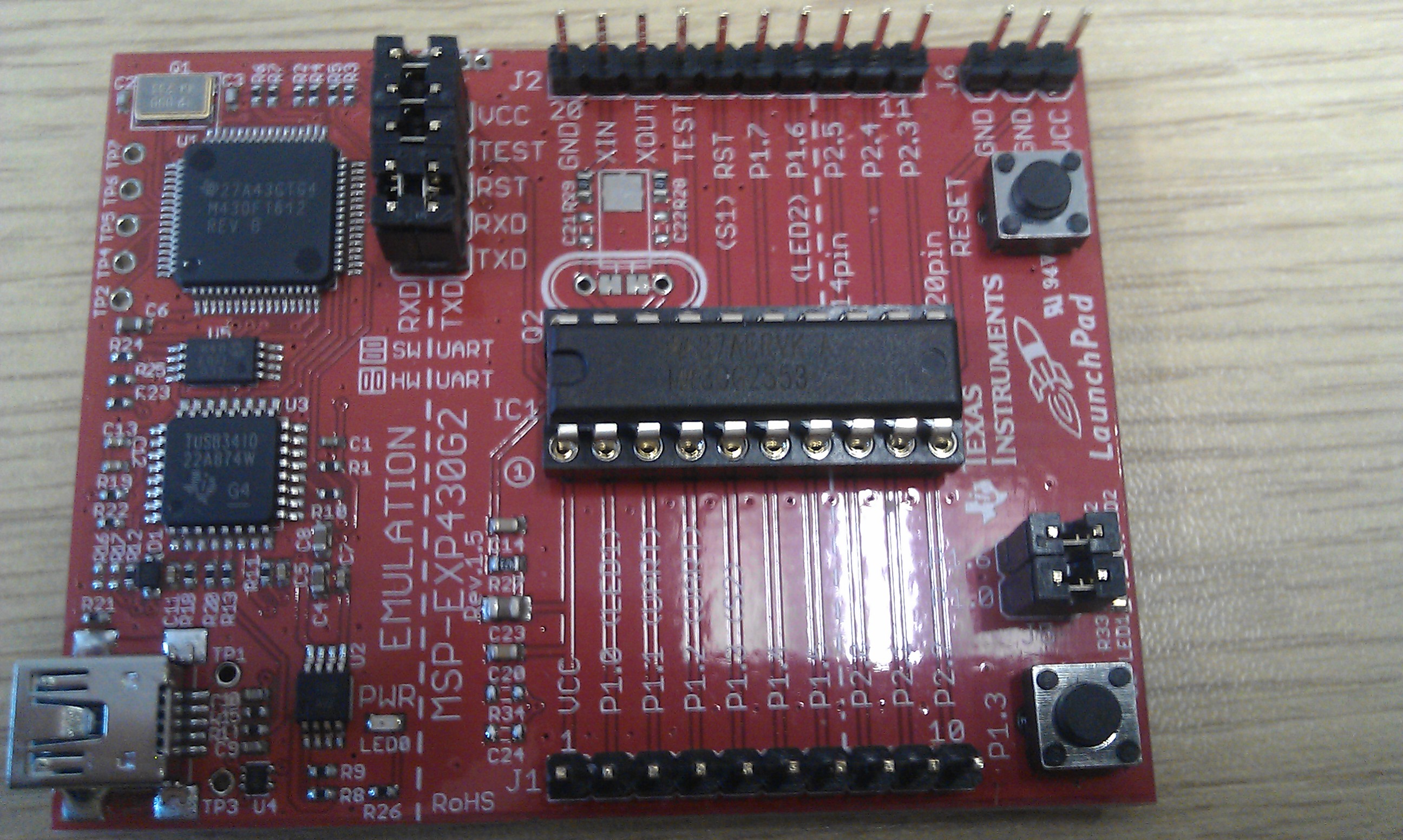
Note: Because this uses the hardware UART on the MSP430G2553 it is necessary to rotate the RXD and TXD jumpers on J3 by 90 degrees on the lauchpad. When in the correct position the jumpers should be as shown below. The jumpers are shown in the correct orientation in the top left of the picture.

/* Example code demonstrating the use of the hardware UART on the MSP430G2553 to receive
 * and transmit data back to a host computer over the USB connection on the MSP430
 * launchpad.
 * Note: After programming it is necessary to stop debugging and reset the uC before
 * connecting the terminal program to transmit and receive characters.
 * This demo will turn on the Red LED if an R is sent and turn it off if a r is sent.
 * Similarly G and g will turn on and off the green LED
 * It also transmits the received character back to the terminal.
 */

#include "msp430g2553.h";
void UARTSendArray(unsigned char *TxArray, unsigned char ArrayLength);

static volatile char data;

void main(void)

{
 WDTCTL = WDTPW + WDTHOLD; // Stop WDT

P1DIR |= BIT0 + BIT6; // Set the LEDs on P1.0, P1.6 as outputs
 P1OUT = BIT0; // Set P1.0

BCSCTL1 = CALBC1_1MHZ; // Set DCO to 1MHz
 DCOCTL = CALDCO_1MHZ; // Set DCO to 1MHz

/* Configure hardware UART */
 P1SEL = BIT1 + BIT2 ; // P1.1 = RXD, P1.2=TXD
 P1SEL2 = BIT1 + BIT2 ; // P1.1 = RXD, P1.2=TXD
 UCA0CTL1 |= UCSSEL_2; // Use SMCLK
 UCA0BR0 = 104; // Set baud rate to 9600 with 1MHz clock (Data Sheet 15.3.13)
 UCA0BR1 = 0; // Set baud rate to 9600 with 1MHz clock
 UCA0MCTL = UCBRS0; // Modulation UCBRSx = 1
 UCA0CTL1 &= ~UCSWRST; // Initialize USCI state machine
 IE2 |= UCA0RXIE; // Enable USCI_A0 RX interrupt

__bis_SR_register(LPM0_bits + GIE); // Enter LPM0, interrupts enabled
}

// Echo back RXed character, confirm TX buffer is ready first
#pragma vector=USCIAB0RX_VECTOR
__interrupt void USCI0RX_ISR(void)
{
data = UCA0RXBUF;
UARTSendArray("Received command: ", 18);
UARTSendArray(&data, 1);
UARTSendArray("\n\r", 2);

switch(data){
 case 'R':
 {
 P1OUT |= BIT0;
 }
 break;
 case 'r':
 {
 P1OUT &= ~BIT0;
 }
 break;
 case 'G':
 {
 P1OUT |= BIT6;
 }
 break;
 case 'g':
 {
 P1OUT &= ~BIT6;
 }
 break;
 default:
 {
 UARTSendArray("Unknown Command: ", 17);
 UARTSendArray(&data, 1);
 UARTSendArray("\n\r", 2);
 }
 break;
 }
}

void UARTSendArray(unsigned char *TxArray, unsigned char ArrayLength){
 // Send number of bytes Specified in ArrayLength in the array at using the hardware UART 0
 // Example usage: UARTSendArray("Hello", 5);
 // int data[2]={1023, 235};
 // UARTSendArray(data, 4); // Note because the UART transmits bytes it is necessary to send two bytes for each integer hence the data length is twice the array length

while(ArrayLength--){ // Loop until StringLength == 0 and post decrement
 while(!(IFG2 & UCA0TXIFG)); // Wait for TX buffer to be ready for new data
 UCA0TXBUF = *TxArray; //Write the character at the location specified py the pointer
 TxArray++; //Increment the TxString pointer to point to the next character
 }
}

#include “msp430g2553.h”
ORG 0C000h ; Flash location for 16k device
main mov.w #WDTPW+WDTHOLD,&WDTCTL ; Stop WDT
bis.b #BIT0|BIT6,&P1DIR ; P1.x output directions
bis.b #BIT1,&P1OUT
mov.b &CALBC1_1MHZ,&BCSCTL1 ; Set DCO
mov.b &CALDCO_1MHZ,&DCOCTL
mov.b #BIT1+BIT2,&P1SEL ; P1.1 = RXD, P1.2=TXD
mov.b #BIT1+BIT2,&P1SEL2 ; P1.1 = RXD, P1.2=TXD
bis.b #UCSSEL_2,&UCA0CTL1 ; SMCLK
mov.b #104,&UCA0BR0 ; 1MHz 9600
mov.b #0,&UCA0BR1 ; 1MHz 9600
mov.b #UCBRS0,&UCA0MCTL ; Modulation UCBRSx = 1
bic.b #UCSWRST,&UCA0CTL1 ; Initialize USCI state machine
bis.b #UCA0RXIE,&IE2 ; Enable USCI_A0 RX interrupt
loop bis.w #LPM0+GIE,SR ; Enter LPM0, enable interrupts
nop
jmp loop
USCI0RX_ISR ;—————————————————————
testTX bit.b #UCA0TXIFG,&IFG2 ; USCI_A0 TX buffer ready?
jz testTX ; jmp if 0
mov.b &UCA0RXBUF,&UCA0TXBUF ; Echo back received character
cmp.b #’R’,&UCA0RXBUF
jne notR
bis.b #BIT0,&P1OUT ; Turn on P1.0 red LED
notR cmp.b #’r’,&UCA0RXBUF
jne notr
bic.b #BIT0,&P1OUT ; Turn off P1.0 red LED
notr cmp.b #’G’,&UCA0RXBUF
jne notG
bis.b #BIT6,&P1OUT ; Turn on P1.6 green LED
notG cmp.b #’g’,&UCA0RXBUF
jne notg
bic.b #BIT6,&P1OUT ; Turn off P1.6 green LED
notg reti
;——————————————————————————-
; Interrupt Vectors Used MSP430G2xx2
;——————————————————————————-
ORG 0FFFEh ; MSP430 RESET Vector
DW main ;
ORG 0FFEEh ; USCIAB0RX_VECTOR
DW USCI0RX_ISR ;
END
Nice piece of code. For all of them who use the MSP430 GCC Toolchain (like me), must change the lines:
#pragma vector=USCIAB0RX_VECTOR
__interrupt void USCI0RX_ISR(void)
By:
interrupt(USCIAB0RX_VECTOR) USCI0RX_ISR(void)
To be able to compile.
i had issues running this example through ccs. it was throwing error in line 71. worked after changing “data” to “&data” in “UARTSendArray(data, 1);” and changing “volatile char data;” in line 14.
i cant find the edit link for my previous post. should be: and changing “volatile char data;” in line 14 to “static unsigned char data”, but “static char data” will do as well
You are right about the need for &data rather than data as data is a single char variable and not an array so to pass it as a pointer to the function you need to use the &data notation. Static and volatile variables are different. A static variable is simply a variable that exists for the lifetime of the application. Static variables can be global: defined outside of a function and accessible everywhere, or local: defined within a function and only accessible from within that function. Local static variables are created on the first invocation of the function and remain in memory for the function to use when next called.
A volatile variable is one the can be changed without the compilers knowledge for example by an interrupt. This means that whenever this variable is accessed by the program it must be reread from the actual memory location in case it has changed, rather than simply read from the cache or registers on the ALU if it has already been used recently by the program.
In this case data is updated within an interrupt. This means that data can be changed, an interrupt can interrupt an interrupt. We would also like this variable to always exist so it is best defined as static volatile char data
Thanks a lot. I want to write a software to communicate with msp430 in C#. your example communicates with terminal, how can i make connect it to visual studio C#?
Check out this link http://playground.arduino.cc//Main/InterfacingWithSoftware which should get you started. You might also like to look at this example, https://github.com/sebastienjouhans/c-sharp-arduino-service written for the arduino but should work equally well with the MSP 430.
First off – Thank you for this post. It helped me get UART working. Though I am having an issue I can’t seem to resolve. Using an MSP430G2553, and most of the code you have above, I have been successfully able to connect to the uC from my PC, send a char and return it back, and repeat (basically a typing echo). basically:
// Echo back RXed character, confirm TX buffer is ready first
#pragma vector=USCIAB0RX_VECTOR
__interrupt void USCI0RX_ISR(void)
{
while(!IFG2 & UCA0TXIFG));
UCA0TXBUF = UCA0RXBUF;
}
However, when I try to send a string from the uC, the RX interrupt goes into a loop and keeps TX’ing the string over and over to the PC terminal. My code:
#include “msp430g2553.h”
#include
void sendstring (char * str);
int main(void){
WDTCTL = WDTPW + WDTHOLD; // Stop WDT
BCSCTL1 = CALBC1_1MHZ; // Set DCO to 1MHz
DCOCTL = CALDCO_1MHZ; // Set DCO to 1MHz
/* Configure hardware UART */
P1SEL = BIT1 + BIT2 ; // P1.1 = RXD, P1.2=TXD
P1SEL2 = BIT1 + BIT2 ; // P1.1 = RXD, P1.2=TXD
UCA0CTL1 |= UCSSEL_2; // Use SMCLK
UCA0BR0 = 104; // Set baud rate to 9600 with 1MHz clock (Data Sheet 15.3.13)
UCA0BR1 = 0; // Set baud rate to 9600 with 1MHz clock
UCA0MCTL = UCBRS0; // Modulation UCBRSx = 1
UCA0CTL1 &= ~UCSWRST; // Initialize USCI state machine
IE2 |= UCA0RXIE; // Enable USCI_A0 RX interrupt
__bis_SR_register(LPM0_bits + GIE); // Enter LPM0, interrupts enabled
}
// Send the String when RX interrupt executes (every time I type a key in the terminal)
#pragma vector=USCIAB0RX_VECTOR
__interrupt void USCI0RX_ISR(void)
{
sendstring(“Hello World!\n\r”);
}
//Send each char of the str until reaching the end of the str, wait for TX to be ready after each char.
void sendstring(char * str){
int i
for(i=0; i<strlen(str); i++){
while(!IFG2 & UCA0TXIFG));
UCA0TXBUF = str[i];
}
}
I've tried stopping the RX interrupt by putting IE2 &= ~ UCA0RXIE; just after the for loop. This works, however it only works once, any additional key pressing in the PC terminal will not get the RX interrupt to fire and the string does not get sent a second time. I've tried adding IE2 |= UCA0RXIE; inside the interrupt after the sendstring function call, to re-enable the RX interrupt after the sendstring function finishes, but it seems that you can't enable the interrupt from within the interrupt function itself.
I've confirmed that is it not some setting in my terminal program. I see the same response in multiple terminal programs, on windows and linux. The MSP430 is not on the launchpad, its breadboarded to support two PWM signals out of P2.2 and P2.5 based on a timer, but currently I only have the above code loaded into the 430.
Any thoughts on what is going on? Thanks for the help.
I think the problem is with strlen()
Try this function for sendstring()
void UARTSendString(char *TxArray){
// Send a string using the hardware UART 0
// Example usage: UARTSendString(“Hello”);
while(*TxArray)
{
while(!(IFG2 & UCA0TXIFG)); // Wait for TX buffer to be ready for new data
UCA0TXBUF = *TxArray++; //Write the character at the location specified by the pointer and increment pointer
}
}
Dear sir,
I connected the msp430f5529 for UART connection..but my Red and green leds are not responding accordingly as mentioned by you…
/* Example code demonstrating the use of the hardware UART on the MSP430G2553 to receive
* and transmit data back to a host computer over the USB connection on the MSP430
* launchpad.
…
The example code given is for the MSP430G2553. The MSP430F5529 you have is a different chip and will most likely use different pins for the UART and have a different clock speed and so will require different code to correctly initialise the UART.
Sir, how can I use this code for MSP430f5529 launchpad??. Please help me sir…
In the first instance have a look at the msp430f5529 data sheet and see if it has a hardware UART. Then you will need to change the #include “msp430g2553”; to #include “msp430f5529”; and if the register names and Rx/Tx pins are the same it should work.
Hello,
Just wanted to say that after checking about gazilion of source code examples, yours has work at least! So thank you very much!!!
br
Pawel
Hello,
what you made works well.
But as soon as i want to send stuff from outside the Interrupthandler, nothing happens.
What has to be changed for sending outside of an Interrupt?
Greets,
Malte
Well.. i derped. Its sure it cannot send anything while in LOWPOWERMODE!
I just had to remove the LPM0_bits and its works fine now 🙂
Pingback: UART Technology Kit « The Electronics Maker-E in Dana 111
Ben, I just want to say THANK YOU. Your code is the perfect starter code for getting UART going. I wish TI would put this in there msp430ware.
Hello Ben. Many thanks for a nice piece of code. Have you managed to transmit integers from MSP430G2553 to a PC? When I try
int data[2]={1023, 235};
UARTSendArray(data, 4);
garbage appears in terminal window. Could you please advise me what to do.
Milan I suspect you are looking on the Energia terminal which treats all received bytes as ascii characters. In 1023 in HEX is 03 FF converting to ascii you would expect to see two non-printing characters ‘ETX’ and ‘Blank’
Try using the CoolTerm serial terminal to receive the transmitted characters as this lets you view the HEX values.
Benn it was actually Putty, which doesn’t have a HEX viewing functionality. I’ll switch to CoolTerm. Many thanks for prompt reply!
hello benn., What is done by & in the code. I copied the code to the code composer studio and compiled it. It is giving me lot of errors saying amp is undefined.
thank you
Sorry the joys of copying with the clip board
the &= operator i.e a &= b is equivalent to
a = (a&b);
the & operator in the UARTSendArray(&data,1) call is required to as the function where this is used expects the first parameter to be a pointer. if data was an array i.e. data[] = “hello” then by default data is a pointer so you can simply call the function as UARTSendArray(data,5). However if data = ‘a’ then data is not an array so data is not treated as a pointer. This means if you wish to pass this to to the UARTSendArray function you first need to create a pointer to the variable data i.e.
char data = ‘a’;
char *datapointer; // create a pointer that points to a char
datapointer = &data; // reference the pointer to the char data
UARTSendArray(datapointer,1)
This can also be done in a single line
UARTSendArray(&data,1)