A photo-interrupter consists of a light source typically and LED and a photodetector with a small free space optical path between them. It is placed into the system such that a moving part of the system breaks the beam, e.g. a disk with a single hole in it that is attached to a motor shaft, each time the disc rotates such that the hole in the disc is between the LED and the photodetector light is able to reach the photodetector. In applications where you simply want to count the presence of light or not then you would like to use a device that provides a digital output. A phototransistor provides this kind of operation. A phototransistor is a two terminal device that is switched on when light is incident on the detector (essentially it has the same structure as a conventional BJT but the base input provided by the optical input.) To use this as an input to the micro controller we are going to simply treat it as a light activated switch.
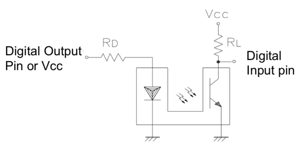
To interface the KTIR0611S Photo-Interrupter to the MSP430G2553 micro controller we are essentially going to use the circuit that is on page 3 of the DataSheet, and reproduced in the fig. 1 below.
The important parameters are the LED forward current If = 20mA and the forward voltage Vf = 1.2V. We will connect the LED to one of the Digital outputs on the micro controller, however as the logic high voltage is 3.3V we need to include a resistor in series with the LED to limit the LED current. As the diode forward voltage is 1.2 volts we need to drop 2.1V across this resistor, when drawing a current of 20mA. Therefore using ohms law we can calculate that the resistance should be Rd = V/I = 2.1/0.02 = 105Ω.
The receiving phototransistor acts as a light dependent switch turning on when light is present. We can then connect this to the micro controller in the same way as we would connect a physical switch. We could use the internal pull-up resistors to supply Vcc however these tend to be about 300kΩ which may make the response time a little slow, so I would recommend a 4.7kΩ external pull-up for RL and leave the internal pull-up disabled.
