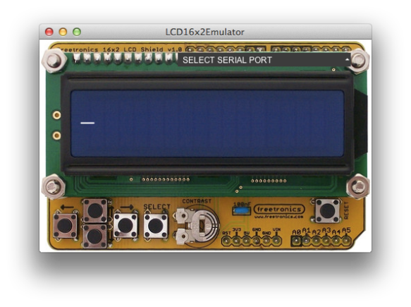
This page details the development and usage of a program that emulates a 16×2 character LCD display. These displays are often interfaced to microcontrollers to provide a user interface. The emulator is designed to allow you to test your microcontroller code with out having to interface a real display to the micro controller. It communicates via the serial port over USB from the host computer to the microcontroller. It will readily work with the TI MSP430 Launchpad and Arduino microcontrollers.
This program emulates the old style LCD & Keypad shield from Freetronics.com the new style one is available here.
The program runs on Windows, Linux ands Mac OS X and is available here along with the source code. It was written in Java using Processing 2. The source code uses the controlP5 library to implement the drop down menu.
You can test the operation of the emulator without connecting to a micro controller, using the keyboard to enter characters, including backspace. You can also use the mouse to operate the keys. The arrow keys will move the cursor.
To communicate with the micro controller you will need to first connect the microcontroller to your computer and then use the dropdown box to select the correct serial interface. On a Mac this is something like “/dev/tty.uart-10FF49F37B51335A”, on Windows “Com5”.
Testing Operation
To test the operation use a simple serial echo program on the micro controller that simply echoes the received characters back to the computer.
Simple serial echo for MSP430 Launchpad with MSP430G2553. Note this program uses the hardware UART so you need to ensure that the TXD and RXD jumpers on the launchpad are rotated the correct way.
/* Example code demonstrating the use of the hardware UART on the MSP430G2553 to receive
* and transmit data back to a host computer over the USB connection on the MSP430
* launchpad.
* It is necessary to rotate the jumpers RXD and TXD as indicated for the HW UART.
* Note: After programming it is necessary to stop debugging and reset the uC before
* connecting the terminal program to transmit and receive characters.
* This demo simply echos the received character back to the terminal
*
* Benn Thomsen, Sept 2014
*/

#include "msp430g2553.h"

void main(void)

{
WDTCTL = WDTPW + WDTHOLD; // Stop WDT

P1DIR |= BIT0 + BIT6; // Set the LEDs on P1.0, P1.6 as outputs
P1OUT = BIT0; // Set P1.0

BCSCTL1 = CALBC1_1MHZ; // Set DCO to 1MHz
DCOCTL = CALDCO_1MHZ; // Set DCO to 1MHz

/* Configure hardware UART */
P1SEL = BIT1 + BIT2 ; // P1.1 = RXD, P1.2=TXD
P1SEL2 = BIT1 + BIT2 ; // P1.1 = RXD, P1.2=TXD
UCA0CTL1 |= UCSSEL_2; // Use SMCLK
UCA0BR0 = 104; // Set baud rate to 9600 with 1MHz clock (Data Sheet 15.3.13)
UCA0BR1 = 0; // Set baud rate to 9600 with 1MHz clock
UCA0MCTL = UCBRS0; // Modulation UCBRSx = 1
UCA0CTL1 &= ~UCSWRST; // Initialize USCI state machine
IE2 |= UCA0RXIE; // Enable USCI_A0 RX interrupt

__bis_SR_register(LPM0_bits + GIE); // Enter LPM0, interrupts enabled
}

// Echo back RXed character, confirm TX buffer is ready first
#pragma vector=USCIAB0RX_VECTOR
__interrupt void USCI0RX_ISR(void)
{
P1OUT |= BIT6;
while (!(IFG2&UCA0TXIFG)); // USCI_A0 TX buffer ready?
UCA0TXBUF = UCA0RXBUF; // Echo back received character
int i = 10000; // Delay so you can see the green LED flash as Data is received
while(i-->0) P1OUT |= BIT6; // This delay is blocking
P1OUT &= ~BIT6;
}
Using in projects
The serial port is used to send and receive 8bit bytes that are interpreted as ASCII characters. The ASCII codes used to represent the keys on the keypad are given in the table below. All other ASCII codes are interpreted as normal.
| Key | code (Dec) |
| Left | 14 |
| Right | 15 |
| Up | 16 |
| Down | 17 |
| Select | 18 |
| Reset | 19 |
